Pipe Sizing
Use the table below to determine the pipe sizing you require for your installation:
- Select the flow rate of the compressor.
- Select the distance between the compressor and the furthest most point of the installation.
- Cross the lines of flow rate and distance columns to establish the size of the pipe you require.
- Example - 42cfm compressor with a maximum pipework distance of 200 metres (to the furthest usage point) will require a 32mm pipework system.
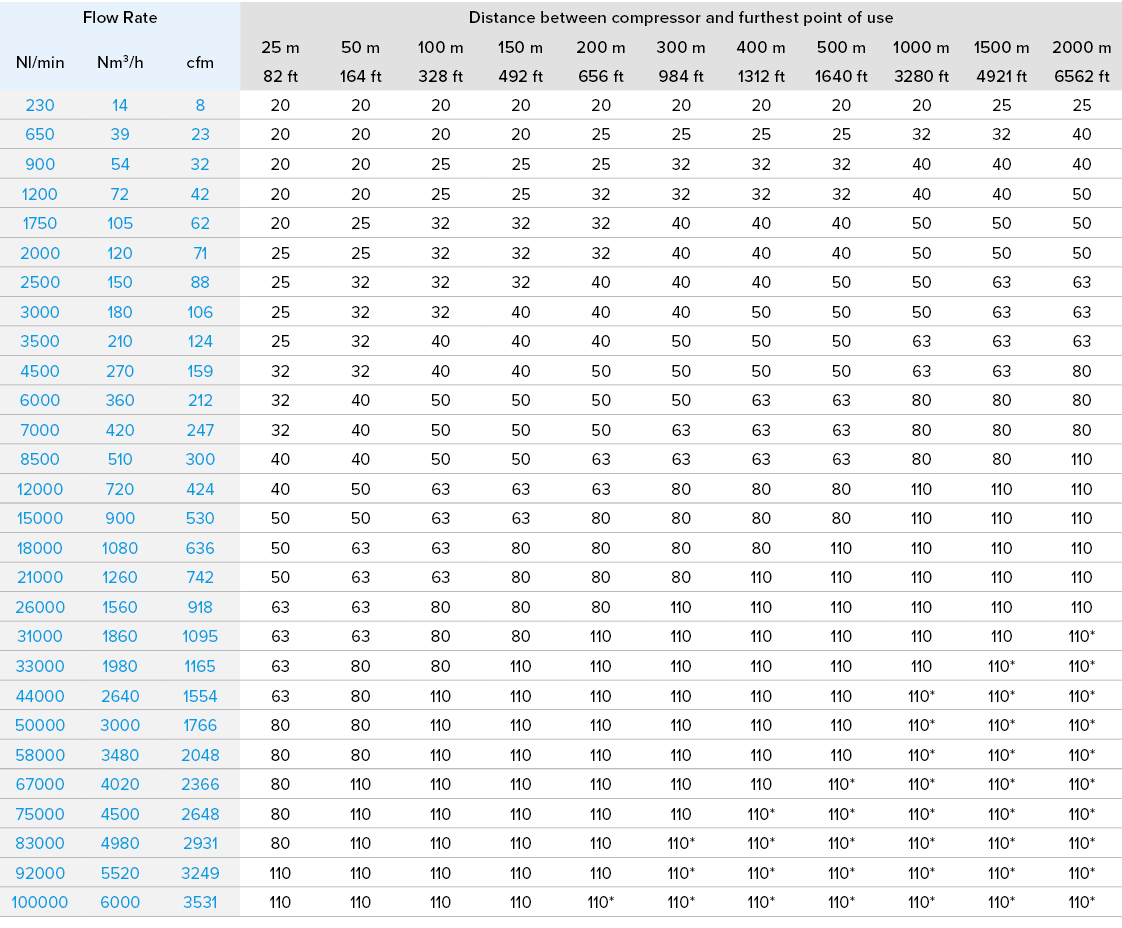
Pressure 7 bar - Total pressure drop 4%
*= Pressure drop is greater than 4%
Click here to download our sizing guide
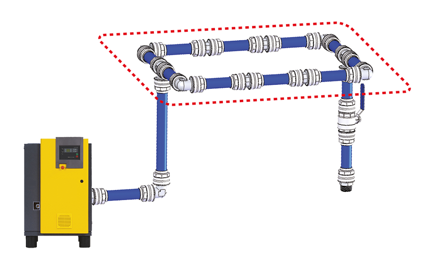
LOOP SYSTEM
Ring main
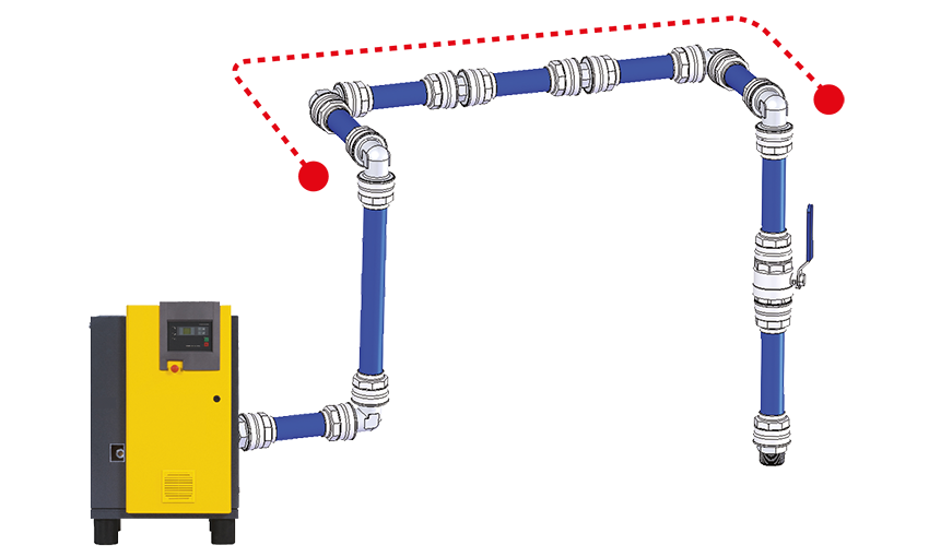
LINEAR SYSTEM
Header
INDICATIVE FLOW RATES
Compressors to 7 Bar

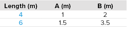
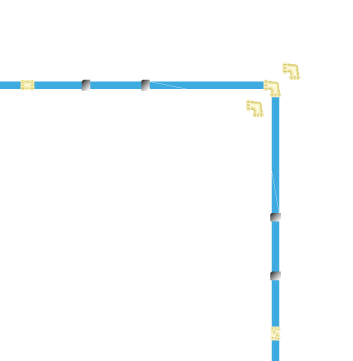
EXPANSION & CONTRACTION DUE TO HEAT
To calculate the linear expansion/contraction we can use the following formula: ΔL = ΔT x L x a
ΔL = Linear expansion/contraction in mm
ΔT = Heat variation between the operating temperature and the installation one at °C
L = Tube length in m
a = Linear expansion factor, for the aluminium is 0.024 mm/m °C
The installation has to be positioned giving consideration at the two ends to free space which permits the expansion - contraction and supports have to be fixed as shown in the illustration: